The JavaScript Raytracer
"Teaching amateurs what raytracing is all about... one... pixel... at... a time."
Table of Contents
About
YKYHBRTLW...
...you create a raytracer in an obscure scripting language that, by nature, makes it completely useless - just for the fun of it.
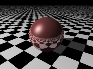
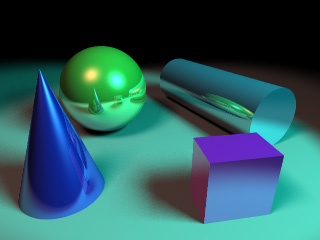
Raytracing, the creation of realistic images by duplicating the mathematical properties of the Real World, has always fascinated me. Since I was a kid, I always wanted a "3D program" to work with. Of course, I had no idea of the complexity involved in using one, and certainly not in creating one. Nonetheless, here is my first self-written 3D graphics renderer ever: The JavaScript Raytracer Version 2.0.
If you're not familiar with it, JavaScript is a scripting language used in web pages to make them dynamic. It has extensive capabilities, and very few web pages really take full advantage of them. This page, I believe, is one of those few.
Raytracers work by tracing the path of light backwards. They start at the position of the camera, and go out until they hit an object. The point at which the object is hit is tested to see if it's in shadow or not, and if the object is reflective or transparent, more rays are shot in order to get the color of light being reflected or transmitted. This is all done through vector math.
 I wrote nearly this entire program from scratch. I learned how Perlin Noise works through my work with POV-Ray, a freeware raytracer (much more powerful than this one). The rest of the algorithms I figured out on my own with the aid of some brief explanations here and there (such as the one you just read). I calculated all of the ray-object intersections by hand with pencil and paper, and figured out all of the logic on my own. I looked things up occasionally only to confirm that I had done them right. Naturally, I couldn't have done it without having taken certain math classes or without my experience with POV-Ray, but this has been one of my most successful projects, and I'm very happy with how it turned out.
The original version of this raytracer was fairly simple. It had a few objects with minimal texturing capabilities, and the user could change the camera's position. The newer version took a few months of work, and allows the user to create his or her own scene. A number of bugs in that implementation have been fixed, and numerous features have been added.
Using the Interface
The more mathematically inclined you are, the easier you will find this. If you're not interested in creating your own scene just yet, don't worry: there are some preset ones already set up for you.
Select a preset from the "Load Preset" dropdown menu, and click "Load." If you're using a standards-compliant browser, you should see some items appear in the "Created Objects" and "Objects In Scene" lists. If you then click the "Render" button at the bottom of the page, the image should start rendering in your browser. Note that at any time, you can click "Cancel Render" to stop a render in progress. When a render has finished or has been cancelled, a button labelled "Remove Display" should appear. By clicking this, you will permanently remove the rendered image from the screen. This button is available because leaving the image there can slow the display of the page. Before performing a render, however, you may want to change the render settings.
The Render Settings
All of the render settings are available in a box labelled "Render Settings," just above the "Render" button. They will take effect whenever a new render begins. The following settings are available:
Resolution
The resolution is the size (width by height) of the image in pixels. A good setting for testing a scene is 40 x 30. A good setting for getting a good view of a scene is 100 x 75, or 160 x 120. If you're feeling ambitious, you might try 320 x 240. Don't attempt 640 x 480 if you don't have more than 256 MB of RAM: JavaScript is not good at saving memory.
Pixel Size
By increasing the pixel size, you can make the image larger. This gives it a pixellated look, but can be helpful for getting a close-up view. Click the "Update" button to cause this setting to take effect in the middle of a render.
Anti-Aliasing
Anti-Aliasing is a method which reduces jagged edges in an image. Normally, one ray is shot for each pixel to determine the color of that pixel. When two adjacent pixels in the image are of very different colors, however, it is useful to shoot more rays for those pixels (this is called "supersampling"), to more accurately determine their colors. Specifically, when the sum of the differences of the red, green, and blue values of the two pixels is greater than the value specified for "Anti-Alias threshold," the two pixels will be supersampled. A threshold value of 3 will cause no anti-aliasing, and a value of 0 will cause every pixel in the entire image to be supersampled. A good quality value is 0.3.
The number of extra samples in a supersampled pixel can be specified by the "Anti-Alias depth" value. This number will be squared; for instance, the default value of 3 will create a square of 3x3 samples, evenly spread throughout the pixel. A value of 1 is pointless, since each pixel already gets one sample by default. For simple tests, a value of 2 is sufficient. 3 will do well for a final render, but you may choose to go as high as 4 for extreme quality.
The "Anti-Alias jitter" value will randomly alter the position of the extra samples. A value of 0 causes no jittering, and a value of 1 will create much randomness in where the extra samples are taken. Values greater than 1 may cause the samples to overlap each other or leave the edge of the pixel, and are not recommended (although this can create an interesting effect).
Checking the "Use directional anti-aliasing" checkbox will cause pixels to only be supersampled horizontally when the threshold is passed between two horizontally adjacent pixels, and vertically when it's passed between two vertically adjacent pixels. This can reduce the number of extra samples. If you use this option, keeping the "Anti-Alias depth" value odd will avoid throwing away previously taken samples. This feature may be somewhat buggy; I didn't want to take extra time to fix it before release.
Display image while rendering
While testing an image, it can be nice to see it appear as it is rendered. However, due to the slow nature of browsers in displaying tables with hundreds of single-pixel table cells, this can also be very slow. Uncheck this checkbox whenever you do a render and want to avoid this extra speed loss. When the render is finished, you can click the "Display Rendered Image" button to show the image. This may take a long time to complete, so be patient if your browser freezes up during this process.
Creating Scenes
One of the real powers of The JavaScript Raytracer 2.0 is the ability to create your own scene. At the top of the page are three lists. The leftmost is a list of types of objects that you can create. The middle one is a list of objects that you have created. These can be edited, removed, or duplicated with the respective buttons. The rightmost list is the list of objects that will actually appear in the scene. Objects can be placed in the scene and removed from the scene with the "->" and "<-" buttons, respectively. When the "Render" button is clicked, the scene will be rendered with all of the objects in the rightmost list. There must be exactly one camera in that list to render the scene; no more and no less.
 You should note that you can only place Cameras, Light Sources, and physical objects (Spheres, Boxes, Unions, etc.) in the scene. However, you are still allowed to select "lower level" objects (like Textures, Transformations, etc.) from the Available Objects list. When you create these lower level objects, they will appear in the Created Objects list, but you will not be able to move them into the Objects In Scene list. The only reason for creating lower level objects is so that you can copy them into higher level objects later on. This can help you avoid the trouble of recreating the same Texture, for instance, more than once. We'll see how to do this in "Sub-Objects."
To create an object, click on one of the types of objects in the left list and click the "Create Object" button. A box with settings for the object will appear. The first thing you can set is the name of the object. This is what the object will be referred to as when you finish it and it appears in the Created Objects list.
At the bottom of the box are "OK" and "Cancel" buttons. If you click the Cancel button, the object will not be created. If you click the OK button, it will be created and will appear in the Created Objects list.
Object Property Types
The other settings that appear in the box are specific to the type of object that you are trying to create. These are the properties of the object. They may be numbers, vectors, colors, checkboxes, or dropdown menus. In addition, there may be buttons that you can click to edit sub-objects. As a general rule, if you're editing an object and you don't know what a property does, you can safely leave it alone because most default values are meant to have no effect on the object. Numbers, checkboxes, and dropdown menus are fairly self-explanatory. The more complicated property types will be discussed here.
Vectors
A vector is a position in three-dimensional space. It is specified by X, Y, and Z coordinates, written in the form <x,y,z>. By default, X is to the right, Y is up, and Z is forward. This is called the "Left Handed" coordinate system. In actuality, X, Y, and Z can be any directions you want them to be in, just as long as you're consistent. However, the default "simple" camera type assumes that you're using the Left Handed coordinate system. You can change this to the "Right Handed" system in your Camera object if you prefer. If the concept of vectors is new to you, just assume that X is to the right, Y is up, and Z is forward. For example, the vector <3,5,-4> is therefore three units to the right, five units up, and four units backwards.
Colors
Colors are specified by the amounts of Red, Green, and Blue light in them. Each of these values can be a number from negative to positive infinity, but you usually want to stick to values between zero and one. Negative colors create weird effects that aren't found in nature, and a value of one is as bright as your computer screen can handle. Note that it's safe to specify a value greater than one for any of the red, green, or blue values, if you know that it's going to be dimly lit or in shadow, so that it doesn't appear that bright on screen. Colors are expressed in the form rgb(red,green,blue). For instance, rgb(1,0,0) is pure red, rgb(.3,1,1) is light cyan, and rgb(0.5,0.25,0) is dark brown. Naturally, rgb(0,0,0) is black (no light) and rgb(1,1,1) is white (when fully lit).
Sub-Objects
A sub-object is an object within another object. For instance, Spheres (and many other types of objects) have Texture and Transformation sub-objects. When an object has a sub-object, there will be a button you can click to edit that sub-object.
Editing a sub-object works just like creating an object: when you click the button, a box will appear in its place with OK and Cancel buttons, and you can set the settings for the sub-object. Note that if you click the "OK" button in an object while one of its sub-objects is still open, it will be as though you had clicked "OK" in the sub-object first. Similarly, if you click "Cancel" in an object while one of its sub-objects is still open, it will be as though you had clicked "Cancel" in the sub-object first.
Certain types of sub-objects (for instance, textures) also have "Save Copy" and "Copy From Saved" buttons next to "OK" and "Cancel." By clicking the "Save Copy" button, you can save a copy of the sub-object into the Created Objects list. If you click the "Copy From Saved" button, you will be prompted to enter the name of a previously created object to copy into the current sub-object. For instance, if you create a Texture normally, and then create a Sphere, enter the sphere's Texture sub-object, and click the "Copy From Saved" button, you will be able to load a copy of the texture that you already created.
Arrays
Some object types, such as Transformations, rather than having editable properties laid out, have list interfaces where you can add an arbitrary number of objects in a sequence. In these objects, there are two lists to work with. The one on the left is a list of the possible object types you can add to the array. The one on the right is a list of the elements in the array itself.
To create an element, select its type from the list on the left and click the "Create" button. An editable object will appear as normal. When you finish editing the object and click "OK," the object will disappear and be added to the list on the right.
Objects in the list on the right can be edited, removed, or duplicated with the respective buttons. They can also be moved up or down in the list with the "Move Up" and "Move Down" buttons to change their order.
Note that you can't edit more than one array element at once.
Object Types
Here is an overview of the different types of objects that you can create and what their properties mean.
Scene Level Objects
These objects can be placed in the scene itself. All of these objects except for Light Sources and Cameras are actual 3D shapes that have surfaces and volume. Before going into the different types of objects, we will discuss some properties that apply to all of these 3D shapes.
Object Modifiers
All 3D shapes share the following properties that can be set:
- Inversed
All 3D shapes have a mathematically defined "inside" and "outside." (For instance, the inside of a sphere is the set of points whose distance to the sphere's center is less than or equal to the sphere's radius.) For the purpose of Intersections and Differences, sometimes you want the outside of an object to be considered its inside. Check this checkbox to invert the object in that way.
- Casts Shadows
Uncheck this box if you don't want the object to cast shadows. Also, you may want to uncheck this box for objects whose shadows won't be visible (for instance, a ground plane), since this will speed up the render.
- Transformation
Shapes can be rotated, translated, scaled, and otherwise linearly transformed after their creation. See Transformations.
- Texture
Textures can be applied to shapes to change their surface properties. See Textures.
Textures are applied to objects after transformations are applied. If you want an object's transformation to apply to its texture also, then use the "Save Copy" and "Copy From Saved" buttons to copy the object's transformation into the function pigment's transformation.
Spheres
Spheres are round things. Yup. Spheres have the following properties:
- Center
The center of the sphere.
- Radius
The radius of the sphere (half its diameter). In other words, the distance from the center of the sphere to the edge of the sphere.
- Other Properties
Spheres also have all the properties listed in Object Modifiers.
Boxes
A box has six sides and can have any length, width, or height. It is always axially aligned (its edges are parallel to the X, Y, and Z axes). If you want to orient your box otherwise, you should rotate it. Boxes have the following properties:
- Corner 1
One of the corners of the box.
- Corner 2
The opposite corner of the box.
- Other Properties
Boxes also have all the properties listed in Object Modifiers.
Planes
Planes are infinitely large flat shapes. They are typically used for the ground or for clouds. Planes have the following properties:
- Normal
The normal of a plane is the vector which is perpendicular to it and points straight out of it. For instance, a ground plane has the normal <0,1,0>, which is straight up. Note that the normal vector points towards the "outside" of the plane, and the "inside" of the plane is considered to be everything on the opposide side.
- Distance Along Normal
By default, a plane will be centered at the origin (<0,0,0>). If you want to make your plane higher or lower, change this value to move it along the normal vector you specified.
- Other Properties
Planes also have all the properties listed in Object Modifiers.
Cylinders
Cylinders are round tube-shaped objects. They have the following properties:
- End 1
The center of one of the ends of the cylinder.
- End 2
The center of the other end of the cylinder.
- Radius
The radius of the cylinder. (In other words, the distance of the surface of the cylinder from the line between End 1 and End 2).
- Ends Open
By default, cylinders have caps at the ends. Uncheck this checkbox to create a cylinder that has no surfaces on the ends, and can be looked through from one end to the other.
- Other Properties
Cylinders also have all the properties listed in Object Modifiers.
Cones
A cone is like a cylinder except that its radius can be different at each end. Using negative radii for one of the ends will create a cone that meets a point inbetween the two ends. Often, one of the radii are zero, but this is not at all required. Cones have the following properties:
- End 1
The center of one of the ends of the cone.
- Radius 1
The radius of the cone at end 1.
- End 2
The center of the other end of the cone.
- Radius 2
The radius of the cone at end 2.
- Ends Open
By default, cones have caps at the ends. Uncheck this checkbox to create a cone that has no surfaces on the ends, and can be looked through from one end to the other if both radii are positive.
- Other Properties
Cones also have all the properties listed in Object Modifiers.
Unions
A union is the mathematical union of multiple shapes. Simply put, it's just a way of holding multiple shapes in a single object. Mathematically, it's the shape which shares the surfaces of all the shapes in it, and has volume wherever any of the shapes within it have volume. You can place objects in a Union by editing its "Objects" sub-object. Unions also have all the properties listed in Object Modifiers.
Intersections
An intersection is the combination of multiple shapes. It exists wherever all of the shapes within it converge. For instance, the intersection of a sphere with a plane looks like a sphere that has had part of it chopped off. Mathematically, it's the shape which has volume only where all the shapes within it have volume, and has a surface whereever any of the shapes within it have a surface and all the rest of them have volume. You can place objects in an intersection by editing its "Objects" sub-object. Intersections also have all the properties listed in Object Modifiers.
Differences
A difference is the result of cutting certain shapes out of others. You can set the positive shapes by editing the "Positive Objects" sub-object, and you can set the shapes to be cut out from them by editing the "Negative Objects" sub-object. Internally, differences are the intersection of the union of all the positive objects and the inverses of all the negative objects. Differences also have all the properties listed in Object Modifiers.
Light Sources
A light source is a point in space which emits light. Light Sources have the following properties:
- Position
The position of the light source in space.
- Color
The color of light emitted from the light source.
- Area Light
This sub-object allows you to set the light source so that it creates soft (blurred) shadows. This slows rendering but can create very nice effects. To test if a given point is in shadow, multiple samples on the area of the light source are checked to see if light reaches the given point from them. The area of the light source is defined by two direction vectors. If light from all or none of the samples reaches the given point, that point will be considered fully lit or in shadow. If light from some of the samples reaches the given point, and light from others doesn't, then more samples on the area light will be tested. Area lights have the following properties:
- Use Area Light
Check this box to specify that you want to enable the area light feature.
- Dimension 1, Dimension 2
These two vectors specify the size and position of the parallelogram that is the light source's area. A light source centered at <0,0,0> with the dimension vectors <1,0,0> and <0,1,0> will span the square in space from <-1,-1,0> to <1,1,0>. If one of these vectors is <0,0,0>, then the area light will be one-dimensional.
- Minimum, Maximum Sampling Depth
These values specify the number of samples that will be taken from the point of the area light. A value of 0 specifies a 2x2 square of samples on the parallelogram. 1 specifies a 3x3 square, 2 specifies a 5x5 square, etc. Each depth level adds sampling points inbetween the ones of the previous depth. The minimum sampling depth is the depth level that will be tested for all points in the entire scene. This should be zero unless that causes artifacts. If you have pointy objects or objects with sharp transitions in the scene, then you may need a value of 1. If the area light is large, you may even have to make it 2, but that will be really slow. If testing all the samples up to the minimum sampling depth shows that light reaches a given point from only part of the area light, then more samples will be taken, up to the maximum sampling depth, to figure out more accurately how much light is reaching that point. The benefit of the minimum sampling depth is that it prevents too many samples from being taken at points in the scene which are fully lit or fully shadowed.
- Jitter Amount
This specifies how much to randomly jitter the samples by. A value of 1 is strongly suggested. Sometimes you may even want to go higher than 1; this will cause samples to overlap each other, but they will do so very randomly and it will cause the soft shadows to be blurred even more, especially if anti-aliasing is turned on. This jittering of samples allows you to use much lower depth levels than would otherwise be necessary, in exchange for a slight amount of graininess in the image.
- Spot Light
This sub-object allows you to set the light source so that it only illuminates points within a conical shape eminating from the light source's position. This can be used to create an artistic effect and to increase render speed in areas outside the spot light's cone. Spot lights have the following properties:
- Use Spot Light
Check this box to specify that you want to enable the spot light feature.
- Point At
Set this vector to the point in space that you want the spot light to point towards.
- Outer, Inner Angle
If the angle between a point and the line from the light source's position to the Point At vector is greater than the Outer Angle, that point will not be illuminated. If it's less than the Inner Angle, then the point will be fully illuminated. The area between the two angles will smoothly fall off from fully lit to unlit. Note that 180 is the maximum value that you should specify for either angle (180 degrees encompasses every point in space).
- Transformation
This transforms the light source. Note that if the light source is a spot light, transforming it will not change the inner or outer angles, and the area illuminated by the spot light will remain conical. See Transformations.
Cameras
The camera specifies where you're the scene should be viewed from when it's rendered. You can choose between two different ways of specifying your camera:
- Simple
The simple camera definition is meant to make the camera easy to set up. You can set the following properties:
- Position
The position of the camera.
- Look At
A point in space that the camera should look at.
- Sky Direction
The direction that the sky is in. The default is <0,1,0> (Y). Some people may prefer to use Right Handed coordinates with <0,0,1> (Z) being "up."
- Zoom Amount
The amount the camera should zoom in or out. Greater than one will zoom in, less than one will zoom out, and a negative value will make the camera look in the opposite direction.
- Scene Aspect Ratio
This value should be set to correspond with your resolution settings, unless you want to squish or stretch the image.
- Coordinate Type
Set this to whichever types of coordinates you prefer to work with.
Internally, the simple camera definition is converted to a complex camera definition.
- Complex
The complex camera definition can be very difficult to set by hand for cameras that aren't axially aligned. You can set the following properties:
- Position
The position of the camera.
- Direction
The direction the camera is looking in. The length of this vector compared to the length of the right and down vectors is proportional to how zoomed in or out the camera is.
- Right
The direction to the right from the camera's point of view. The length of this vector changes how stretched out or squashed the resulting image will be horizontally.
- Down
The way down from the camera's point of view. The length of this vector changes how stretched out or squashed the resulting image will be vertically.
Each pixel at position (u,v) in the image, where u and v are between 0 and 1, has a corresponding ray used to determine its color. When you use the complex camera definition, that ray is calculated as follows: its starting position is the camera's position, and it's direction is
direction + right*(u*2-1) + down*(v*2-1).
Cameras can also be transformed by editing the "Transformation" sub-object. See Transformations.
Other Objects
The following objects can be created, but cannot be placed into the Objects In Scene list. The only reason for creating them directly is so that you can copy them into other objects later on.
Textures
Textures define how the surface of an object appears. They consist of two sub-objects: a Pigment and a Finish. Pigments are explained here, while finishes will be discussed later (see Finishes).
You have a choice between two types of pigments: a solid color pigment, or a function defined pigment. The latter will be explained later (see Function Pigments.) A solid color pigment is nothing more than a single color which is applied uniformly to the object.
Finally, textures have an "Overrides parent's texture" checkbox. This applies only to textures of objects that are part of a Union, Intersection, or Difference. Normally, such objects take on the texture of the higher-level object that they're a part of. If this checkbox is checked, however, parts of the higher-level object that are formed by the object in question will take on its texture instead.
Finishes
The Finish of a Texture specifies the surface properties of the object it's applied to. Finishes have the following properties:
- Specular Amount
Specular light is light that is reflected from a light source towards the viewer, creating a shiney highlight effect. This property specifies how bright that effect is. A value of zero will create no highlight, and a value of one will reflect the full intensity of the light source towards the viewer.
- Specular Glossiness
This value specifies how large the highlight is. Smaller values (below 5 or so) create larger highlights for a less glossy look, while larger ones (anywhere from 5 to 20 to infinity) create smaller and smaller highlights, making the surface look shinier. Good values are between 1 and 300.
- Reflection Amount
This value specifies how much light is reflected off the surface of the object (as though it were a mirror). A value of zero is no reflection, while a value of one will create a reflection as bright as the scene itself.
- Diffuse Light Multiplier
This value specifies how much effect diffuse light (light coming directly from a light source) has on the object. A value of zero will make the object ignore light sources (causing it to look like it has a black pigment), and a value of one will cause its pigment to take full effect.
- Ambient Light Multiplier
Ambient light is the light that's bouncing randomly off of objects, causing things that would otherwise be in shadow to be visible. Accurate simulation of ambient lighting can singlehandedly make a scene look extremely realistic. Unfortunately, The JavaScript Raytracer has only a very simple simulation of this type of light. This value will be multiplied by the object's pigment uniformly, causing it to be slightly lighter than black where light isn't hitting it directly. Setting this value close to 1 will cause the object to appear to "glow."
Function Pigments
Function Pigments can be used in Textures to create a pigment that varies over the surface of an object. In order to create a Function Pigment, you must know some JavaScript. The variable pos is available to you, and is a Vector as defined in vector.js. Your function must return a Color, as defined in texture.js. The global functions noise(vector) and checker(vector) are available. The first returns a value defined by Perlin Noise (this is equivalent to POV-Ray's f_noise3d function and its bozo pattern). It's slow, so use it sparingly. The second function returns either zero or one, corresponding to a checker pattern defined in 3D space. (Note that this checker pattern changes its value right along key places such as the X-Z plane, so be sure to translate it when necessary to avoid floating point errors.) Keep these functions as simple as possible, because they will be evaluated over and over, which slows the render speed.
You can transform your function just like an object by editing the "Transformation" sub-object. See Transformations.
Transformations
A transformation is a way of physically manipulating an object in 3D space. Transformations can rotate, scale, translate, or otherwise linearly transform an object. A transformation consists of multiple components. If it is inversed (by checking the "Inverse" check box), then it will have the opposite effect specified.
Applying a transformation to an object can slow the render speed. However, remember that a transformation with a single component is no faster than a transformation with 100 components. Once you decide you're going to transform an object, you can go crazy with it, because extra components won't take any extra time to compute during the render.
The following components can be added to a transformation:
- Rotation
A rotation rotates the object around either the X, Y, or Z axis by the number of degrees specified. To figure out which way the object will rotate, take your left hand (or your right hand if you're using the right-handed coordinate system) and point your thumb in the positive direction of the axis you're rotating around (for instance, if you're rotating around X, point your thumb to the right). The direction in which your fingers curl is the direction in which the object will rotate. Note that all rotation is done around the axes, not around the center of the object. This means that a sphere placed at <100,0,0> and rotated 90 degrees around the Y axis will end up at <0,0,-100>. Therefore, you may wish to center your object around the origin, then rotate it, and then translate it to wherever you want it to be.
- Translation
Translations shift the object through space. For instance, a translation of <5,0,0> will move an object five units along the X axis.
- Scale
Scaling an object changes its size. A scaling vector of <2,2,2>, for instance, will double an object's size. A scaling vector of <1,0.5,1> will shrink the object to half its size in the Y direction. Note that, like rotating, scaling is done relative to the origin, not relative to the center of the object. Do not scale any of the dimensions by zero, as this will cause a JavaScript error when you attempt to render the image.
- Matrix
Internally, all transformations are converted to a matrix and a single displacement vector. The matrix transformation lets you specify this directly. You can set a vector to map X, Y, and Z to, and a translation vector to be applied afterwards. For instance, setting the "Map X to" vector to <1,1,0> will shear the object vertically. Try it on a simple box if you're interested, but don't be worried if you can't figure this one out. Be careful not to create a matrix transformation that will flatten the object out entirely (for instance, by setting two of the mapping vectors to the same value, or by setting one of them to zero), because this will cause a JavaScript error when you attempt to render the image.
- Transformation
You can use a Transformation as a component of another Transformation. The advantage to this is that you can use the "Copy From Saved" button to use one Transformation within another one.
Workspace Options
Naturally, with so many possibilities, you'll need a way to save your work, so you can come back to it later... and also just in case your browser dies on you. At any point, you can click the "Save Workspace" button in the "Workspace Options" box, just above the Render Settings. This will cause a text box to appear with a long string in it. Copy this string, open notepad (or whatever text editor you prefer), and paste it in. Save it as a text file for later on. Be sure not to alter the string in any way.
To load a workspace, copy the string again, click the "Load Workspace" button, and paste it into the prompt that appears. Click OK and the workspace should load. The objects being loaded will be appended to the objects that are already in the workspace. In order to remove all of the objects in a workspace at once, click the "Close Workspace" button.
There are also some preset workspaces that you can load. Select one from the "Load Preset" dropdown menu, and click "Load." You can edit these workspaces as you wish, or just render them to see what they look like. Some of the presets are actual complete scenes, and some are meant to help you get started on your own scenes.
Some Last Words
 Be patient. Raytracers are generally known for being slow (with some exceptions), and JavaScript isn't known for being fast. A simple image may take overnight to render. So start small, and experiment. Don't attempt high-resolution renders unless your computer has the memory to handle it.
I didn't really create this thing to be useful. I made it to prove to myself that I could do it, to prove to others that JavaScript is not a simple language, and overall just to have fun.
Take a look at the original version. That's what I started with. People liked it so much that I decided I had to expand upon it. I just hope it hasn't lost its novelty. ;)
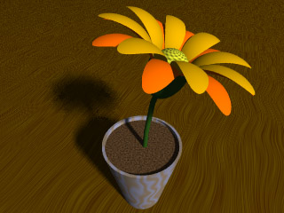
I'd like to thank my beta testers, especially Karl Semich (Te'ja), who found some crucial bugs while modelling the flower (shown here), and my friend Stu, who also discovered one or two significant bugs, and patiently helped me work around an Internet Explorer 5.x memory error. If you find any bugs, please let me know about them. First, please make sure they're really bugs.
The files vector.js (a 3D Vector object), transformation.js (a Matrix Transformation object), and perlinnoise.js (Perlin Noise functions) are available to you in the jsinclude directory. If you want to use them, please do not link directly to them on my server; download them for yourself.
If you enjoy raytracing, I encourage you to look at POV-Ray, a freeware raytracer available for download. It's much better than this one, and a lot faster, of course. I use it all the time. It's a lot of fun. Try it out. If you can figure this thing out, you'll be able to figure it out, also; and it's a lot more flexible. Some absolutely amazing images have come out of that program.
Finally, if you create a cool image, let me know about it. Save your workspace and email me the string, and perhaps a jpeg image. If I get one that I really like, I might even make it one of the presets. But I really just want to see what other people do with this thing.
Good luck, and don't RTL.